 EN

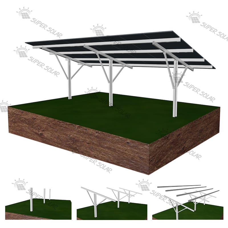
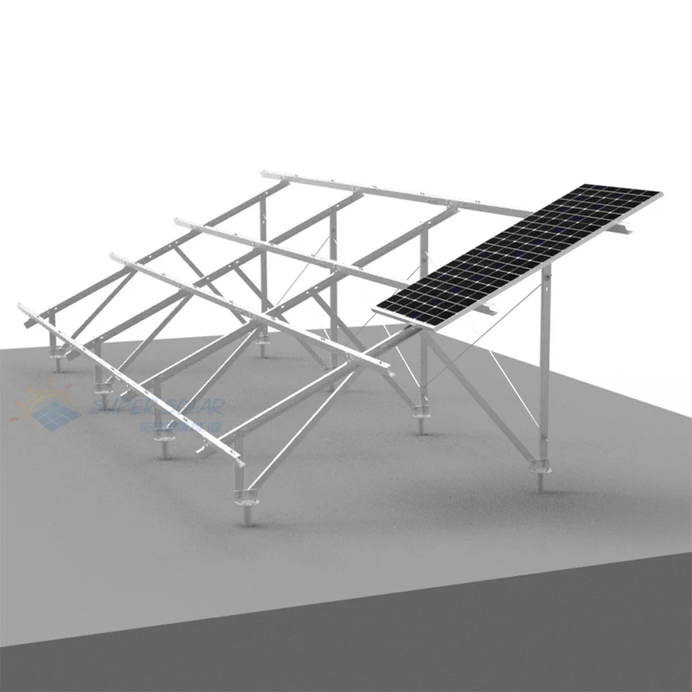

A site with shallow rock or heavily compacted ground removes most of the assumptions that make ground-mounted solar straightforward. Pile driving either stops at refusal or damages the equipment, screw installation slows to a crawl or strips the blade, and excavation for a concrete footing becomes a rock-breaking exercise with its own cost and equipment requirements. Developers who discover this during construction rather than during feasibility typically face a three-way compromise: accept a redesign, accept a schedule slip, or accept a foundation solution that costs more than the original design assumed. None of those outcomes is inevitable, because a solar ground mount rocky soil or hard soil foundation can be designed deliberately, provided the site is characterised properly first.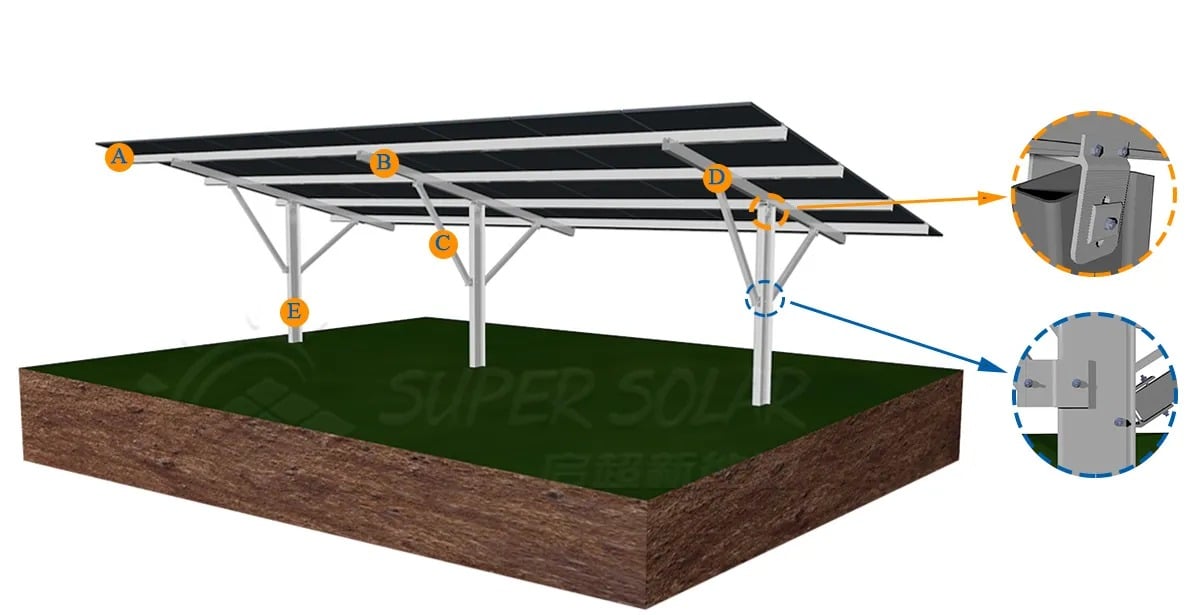
The reason this particular problem rewards preparation is that the ground is not uniformly difficult. Rock depth varies, weathered zones sit above competent rock, and a hard layer at one end of an array may be absent at the other. A design that responds to a single observation will be wrong somewhere on the site, and the cost of that error is highest exactly where the array is most heavily loaded. The practical objective is a solar ground mount rocky soil design that is robust to the variability that actually exists, supported by site records that show what was found and where. A hard soil foundation scheme built on a single observation is not a design; it is a guess with a drawing number. The sections below set out the investigation, the foundation options and the documentation that make this workable.
Start with what can be learned without breaking ground. Geological maps, previous site investigations, historical land use and any nearby construction records can indicate whether rock is likely to be shallow and how it behaves when worked. A visual walkover adds useful evidence: exposed rock in cuttings or drainage channels, vegetation patterns indicating thin soil cover, and local quarrying or earthworks all provide clues. The desk study will not produce a design, but it determines how much investigation is warranted and where it should be concentrated, which is precisely the decision that controls investigation cost.
Ground truth comes from physical investigation. Trial pits show the soil profile and the depth to rock over a small area; boreholes or probing provide a more continuous record along the array lines. Where rock is shallow, a penetration test using the intended production installation method is particularly informative, because it reveals not only the depth of refusal but the installation difficulty, which is the variable that governs time and equipment cost. Investigate along the array rows rather than only at the site entrance, and repeat at intervals that reflect the variability observed, tightening the spacing wherever the profile changes.
Record the depth at which refusal occurred, the nature of the material encountered, whether it was sound or weathered, and any obstructions such as boulders or buried structures. Note whether the hard layer is continuous or forms isolated highs, because isolated highs create local problems that a generic design will not cover. Photograph the exposed profile where trenches or pits are available, and keep the photographs with their locations. This record is what allows a foundation scheme to be designed to the real subgrade rather than to a tabulated summary.
Water influences both constructability and long-term durability. A high water table complicates excavation, requires dewatering and, in some cases, pushes the design towards alternatives that do not break ground at all. Local drainage paths and surface runoff affect the erosion risk around supports and the stability of cut faces on sloping sites. Where the array is terraced across a slope, runoff interception may itself need a design response, particularly on fine-grained soils. On terraced layouts it is also worth checking that runoff from one terrace cannot undermine the foundations of the terrace below it.
Where a competent layer sits close to the surface, anchoring into that layer is often the most reliable approach. Rock anchors grouted into predrilled holes develop high capacity in a small footprint, and micro-piles with a steel core can transfer load into rock or into a harder stratum beneath the surface. Pre-drilling to a defined depth and diameter ahead of pile or screw installation is a common hybrid, allowing a pile to be seated in a pre-formed hole rather than driven to refusal. The design must define the required embedment into competent material, the grout specification where grouting is used, and the corrosion protection for the embedded steel. Because these options depend on the properties of the rock itself, they should be selected only after the hard soil foundation investigation has established what the material actually is.
Ground screws remain usable on some hard ground if the blade can engage and the site is not obstructed, and they retain the advantages of no concrete, no spoil and fast installation. Their limits must be respected, however: refusal in dense gravel or rock, blade damage on obstructions, and reduced capacity in very stiff or dry soils all reduce their viability. Where a screw cannot reach the required depth, the correct response is a different foundation rather than a reduced embedment, because capacity depends on both depth and soil condition. Pilot installations on the actual site are the most reliable way to establish whether screws are practical, and they are usually the fastest way to resolve a disagreement about solar ground mount rocky soil feasibility.
Concrete remains an option where rock is at or near the surface and the design can spread load over a pad on competent material, and where uplift can be resisted by weight plus anchorage. Precast or ballasted systems have the advantage of minimal in-situ work, but they require verification against uplift, and they transfer high bearing pressures to the rock or soil beneath. Where penetration is prohibited entirely, ballast-based designs may be the only means of installation, which makes the uplift verification the decisive calculation in the whole scheme.
The comparison should be made on total installed cost including equipment, time, spoil removal and reinstatement, not on unit price, and it should be made for the solar ground mount rocky soil conditions actually recorded on site rather than for a tabulated average. It should also be made against a clearly stated design basis, so that the chosen foundation is defensible if conditions turn out to be worse than the investigation suggested. Super Solar's ground mount range, described in the ground mounting system overview, is developed around matching the structure to site conditions, and the company offers free project evaluation based on its engineering experience and testing data so that the foundation, interface and racking are designed together for the actual subgrade.
Where uncertainty remains after investigation, on-site testing resolves it. A pull-out test on a production anchor installed by the production method gives direct evidence of uplift capacity, and a lateral test addresses horizontal resistance. Because hard ground often produces variable results, tests should be distributed across the zones identified in the investigation, and each result should be recorded with its location and installation data. The resulting dataset supports both the design and any later conversation with the owner's engineer. Where results vary across the site, the design should adopt the lowest credible value for the zone it governs rather than an average across all zones.
Every foundation design rests on assumptions, and on difficult ground those assumptions deserve to be written down. The design basis should state the assumed rock depth, the assumed material strength, the corrosion allowance, the load cases and factors applied, and the conditions under which the design would need to be revisited. A design that states its boundaries allows a variation to be priced fairly when conditions change on site. A design that hides them converts every surprise into a dispute. The same discipline applies to the racking and the interface, so that a single document explains what the design assumes about the ground it stands on.
For a difficult site, the record is a deliverable in its own right. Keep the investigation logs with locations, the photographs of exposed profiles, the installation records with torque or driving resistance, the test certificates and the as-built drawings showing which foundation type was installed where. This record is what allows a future phase or a neighbouring site to be designed with far less investigation cost, and it is what turns a single project into transferable knowledge. Without it, the same problems are rediscovered at full price.
On hard ground, foundation tolerances tend to be worse than on worked soils, because anchors cannot always be driven to exact position and depth. The racking design should therefore accommodate position tolerance at the interface, and the connection detail should be checked for the range of as-built positions that production installation will produce. Agreeing that tolerance before fabrication is the cheapest risk reduction available on this kind of site. Recording the achieved position of a sample of installed anchors gives an early indication of the tolerance the racking actually has to absorb.
Equipment choice dominates productivity on hard ground. A rig suitable for soft soil may be inadequate, and the replacement may need a larger working platform, better access or more time per installation. Modelling productivity per anchor rather than per hectare gives a more honest programme, and it should be based on the rates observed during pilot installation rather than on a manufacturer's best-case figure. Where the equipment required changes mid-programme, the mobilisation cost of the second rig should be carried in the estimate rather than discovered in the final account.
Because ground conditions are the least predictable part of a solar project, the commercial structure should allow for variation rather than pretending none will occur. Defining unit rates for additional depth, for rock breaking or for alternative anchors converts an unforeseen condition into a priced change instead of a negotiation. Contingency should reflect the quality of the investigation: the less complete the investigation, the larger the contingency that a prudent developer carries. Agreeing unit rates for the likely variations before works begin is usually more valuable than a lower headline price with no mechanism for change.
Share the investigation findings with the supplier early, including the awkward parts. A supplier who understands that rock is shallow can propose a structure and interface that suits the achievable foundation rather than a design that assumes ideal conditions. Provide the load cases, the corrosion environment and the access constraints at the same time, and ask for a documented design basis in return. Super Solar supports free project evaluation and structural calculation for these situations, and can supply drawings and samples for review before an order is released.
There is no universal threshold, because what matters is the capacity that can be developed within the penetrable depth above the hard layer and within the hard layer itself if pre-drilling is used. A site with rock at a modest depth can still suit driven piles if the overlying material is competent and the embedment achievable meets the load case, while a site with a thin overburden over sound rock may not. The practical answer comes from penetration testing with the production method plus pull-out testing, rather than from a general rule.
Sometimes, and only if a pilot installation demonstrates that the blade can reach the required depth in suitable material without damage. Screws tend to fail on this question in two ways: refusal at a depth shallower than required, or blade damage on an obstruction that is not visible from the surface. If either occurs, the honest conclusion is that the site needs a different hard soil foundation, because reducing embedment to fit the anchor rather than the load reverses the design logic. Where a screw can only reach a shallower depth than the design requires, an anchored alternative or a pre-drilled detail is the correct response.
Record the investigation method and locations, the soil and rock descriptions with depths, the refusal depths observed with the production installation method, the groundwater level and the season in which it was measured, the pull-out and lateral test results with installation data, and photographs of exposed profiles with their positions. Add the as-built mapping of which foundation was used where. Together these allow a neighbouring or later phase to be designed with targeted verification rather than a full investigation, and they are the single most valuable deliverable from any hard soil foundation project.
When penetration is not achievable or not permitted, and when uplift can be resisted by verified weight and anchorage. Above-ground options avoid rock breaking and avoid spoil, which can make them attractive on sites where the alternative would require heavy equipment and extended disruption. The decisive check is uplift, because the array behaves like a wing and the design has to keep it on the ground under the governing wind case. Bearing pressure on the material beneath also has to be checked, since a pad concentrates load.
 Hot News
2025-11-03
2025-10-22
2025-01-24
2024-06-12
2024-06-12