 EN

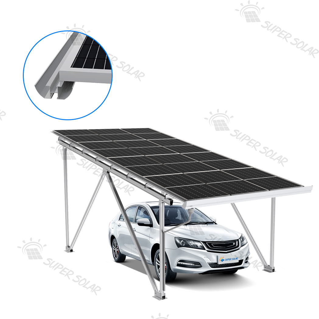

A ground-mounted array is, structurally speaking, a low, wide wing. Wind does not simply push against it; it creates pressure on one face and suction on the other, and the resulting lift can exceed the weight of the structure by a considerable margin. On exposed sites, uplift rather than downward load governs the design of the foundation, the rails and even the module clamps. That is why a solar ground mount high wind design exercise is fundamentally different from designing the same structure for a sheltered inland location, and why copying a design from a calm site to a windy one is one of the more expensive errors in the industry.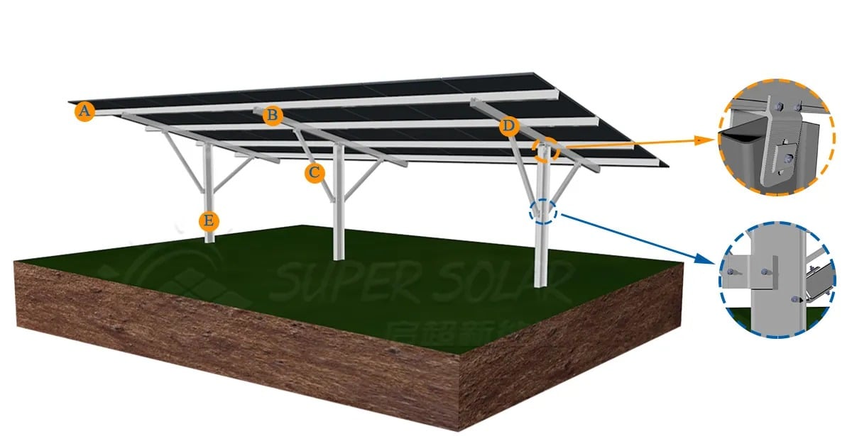
High wind also changes the character of the problem rather than just its magnitude. Gusts are dynamic, and their effect varies with terrain, with the height of the array, with the presence of nearby buildings or vegetation, and with the position of a row within the array. Corner and perimeter zones experience significantly higher pressures than the middle. A design that is adequate on average may therefore fail locally, and the failure often appears first as a loosened clamp or a displaced module rather than as a collapsed structure. The checklist below is organised around the sequence in which those issues should be addressed, and it follows the order in which a solar ground mount high wind design should actually be built up.
Every wind design starts with a value for the site, and that value depends on the return period the project adopts. A basic wind speed read from a national map is a starting point, but the design has to define the reference height, the averaging period and the return period. The project owner, lender or insurer may impose a longer return period than the local minimum, and that requirement should be established at the beginning because it propagates through every subsequent calculation. Where the project relies on a regional map rather than a site measurement, that should be noted in the design file so the source of the value remains traceable.
The site wind speed is converted into a design wind speed by applying factors for terrain roughness, topography and the height of the array above ground. Open farmland, a coastal strip, an urban fringe and a valley with funnelling characteristics all produce different exposure conditions. Local topographic features such as ridges, escarpments and the crests of embankments can accelerate flow and should be identified from survey data rather than assumed. Two sites with the same regional wind speed can therefore produce very different design pressures. Where a site sits close to the boundary between two exposure categories, adopting the more severe category is a conservative choice that is also easy to justify.
The calculation must follow a defined standard and the load factors that standard prescribes. Common frameworks handle wind as a variable action combined with dead load and, where applicable, snow or thermal actions, and the governing combination is often the one with the least favourable balance between uplift and stabilising weight. Documentation should state the standard and edition used, the load factors applied, the reference height and the exposure category. Without that information, a calculation cannot be reviewed, and a calculation that cannot be reviewed is not evidence.
Three different numbers are frequently conflated in supplier discussions: the site's measured or mapped wind speed, the design wind speed used for the structural calculation, and any wind speed quoted from a test. They are not interchangeable. A measured gust is an observation, a design value is a derived quantity with factors applied, and a test result applies to a specific specimen under a specific test method. Keeping them separate in the design file prevents misunderstandably optimistic conclusions, and it prevents claims being made about testing that the project's own documentation does not support.
Foundation design in high wind is dominated by uplift. The dead weight of the structure and the module resists uplift, and the foundation must make up the difference with anchorage. In soils where anchorage comes from friction or bearing, capacity must be established from geotechnical data or from on-site testing rather than from a table. Lateral resistance then has to be checked separately, because a foundation that will not pull out can still slide or rotate under horizontal wind load, particularly where the array is tilted. In a solar ground mount high wind design, the lateral case is the one most often under-analysed relative to its importance.
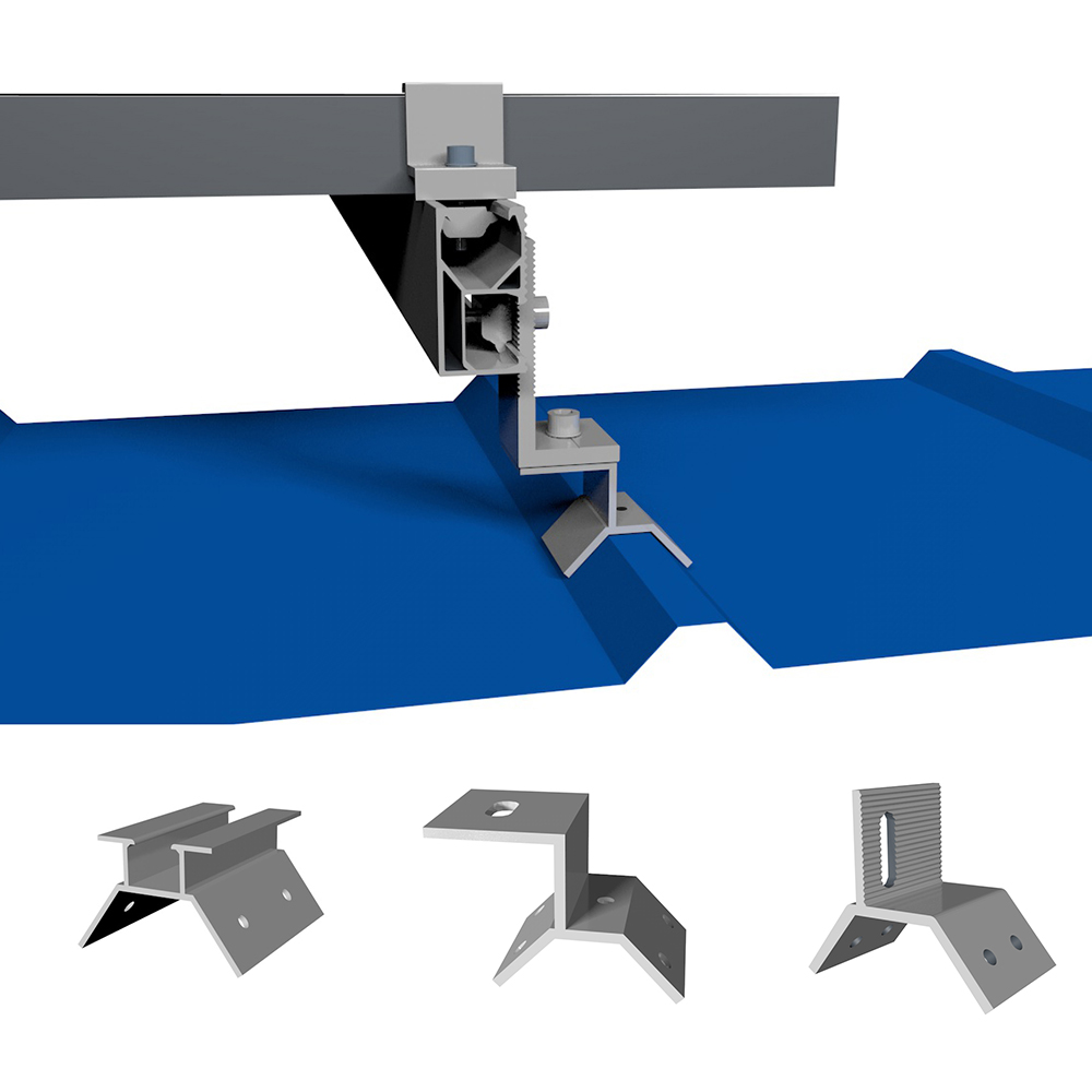
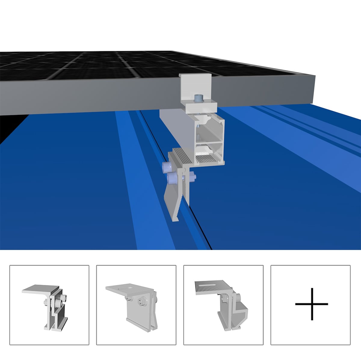
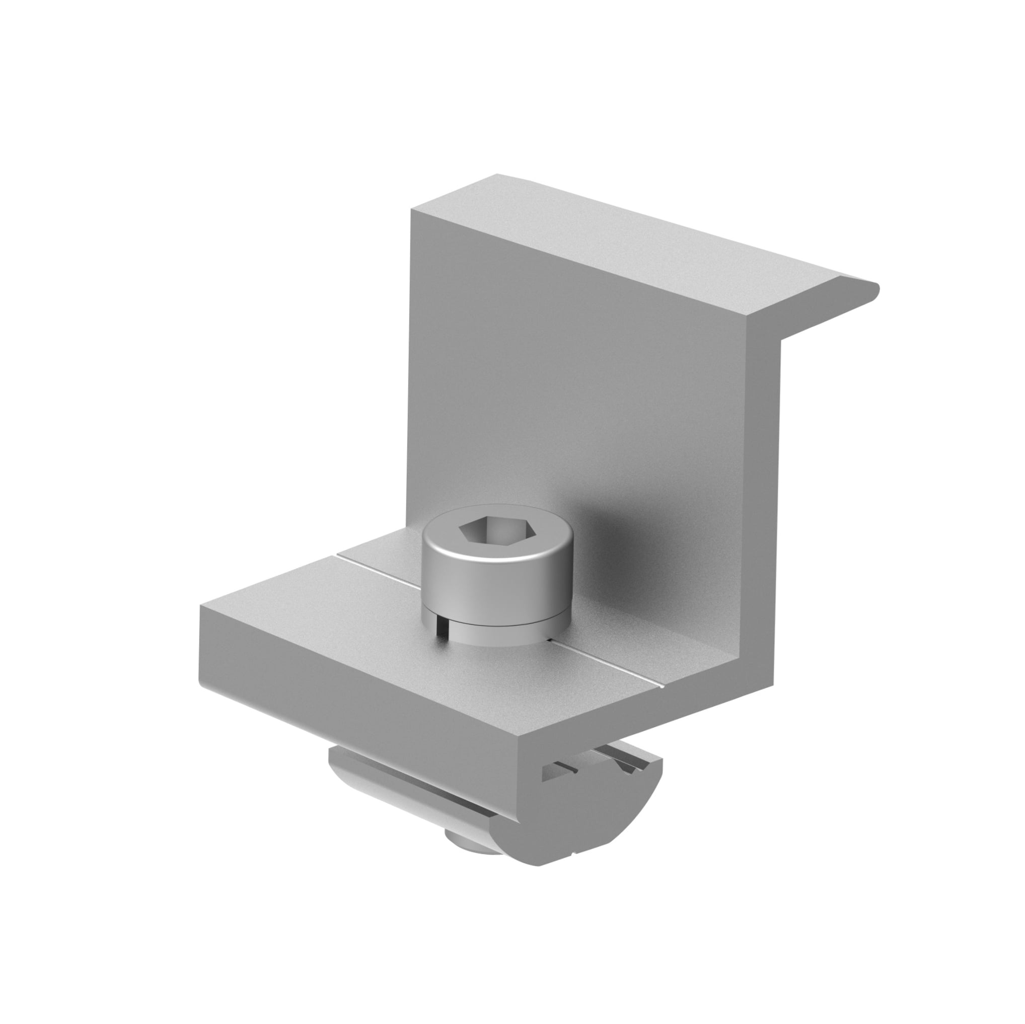
Above the foundation, wind load transfers through the clamps into the modules, from the modules into the rails and purlins, and from those into the supports. Each interface has a capacity limit. Module clamps are often the weakest link, because the clamp bears on a thin aluminium frame extrusion with a defined permitted load per clamping point. In high wind, clamp positions, clamp count and clamp torque become critical, and the module manufacturer's installation instructions frequently specify tighter constraints for high-load zones. Rail sections and support spacing must then be checked for the resulting bending and deflection, and not only for ultimate strength.
Deflection limits exist because excessive movement damages modules and loosens connections, even when nothing technically breaks. In wind, a structure also sees cyclic loading, and connections that rely on friction can work loose over thousands of cycles. Long, lightly damped spans can respond dynamically to gusts, and while large-scale dynamic analysis is rarely warranted for fixed-tilt ground mounts, the design should avoid configurations with very long unsupported spans and should ensure that bolted connections remain tight. Where trackers are involved, the stow strategy becomes part of the wind design rather than an operational detail.
High-wind design should consider what happens if one element degrades. If a single clamp loosens, does the module rely entirely on that clamp, or do the remaining clamps and the frame geometry keep it in place? Redundancy is not free, but on exposed sites it is often cheaper than a repair campaign after a storm season. Progressive collapse should also be considered in long rows, where one failed support can transfer load to its neighbours. The same logic applies to the foundation, where a single support carrying an excessive share of the load is a design weakness rather than an economy.
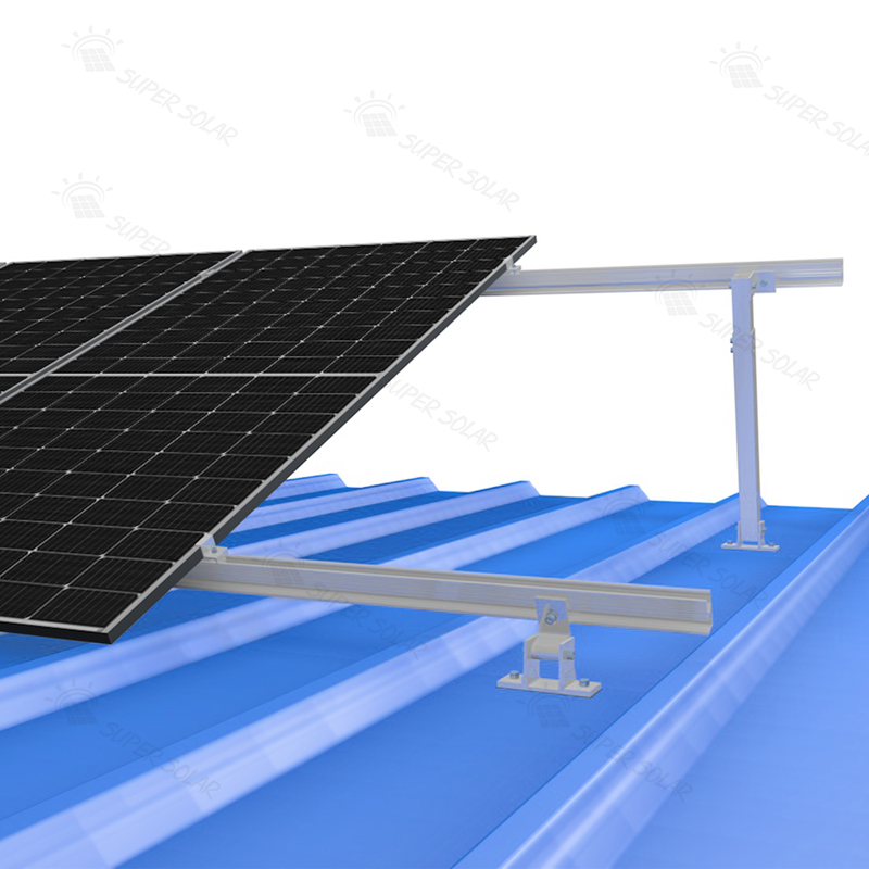
Tilt angle has a strong effect on wind loading, because a steeper array presents a larger effective area to the wind in some directions and changes the pressure distribution around the modules. Reducing tilt is one of the most effective ways to reduce wind demand, and it is often traded against energy yield in the project's optimisation. Row spacing also matters, because closely spaced rows create a more continuous obstacle with different aerodynamic behaviour than widely spaced, isolated rows. This is a design decision that couples the structural and energy models together, and it deserves to be evaluated as such. It is also the most powerful lever in a solar ground mount high wind design, because altering the configuration reduces the load that every downstream component has to resist.
For fixed-tilt structures, there is no stow position, so the design must simply be adequate at all times. For tracking systems, wind stow is a real mitigation, but it only helps if the control system reliably detects the condition and moves the array, and if the stowed geometry genuinely reduces loading. Gaps between modules, open perimeters and the treatment of the array edges all influence local pressures; leaving deliberate openings or avoiding enclosures that trap flow can reduce the peak suction at vulnerable locations. Where the design relies on a stow position to reduce loading, the reliability of the mechanism that achieves it becomes part of the structural case rather than an operational detail.
Wind pressure varies across an array. Perimeter rows, corners and the ends of rows experience higher uplift than the middle, and the design usually reflects that with tighter support spacing or heavier foundations in those zones. Nearby obstructions such as buildings, walls, containers and even dense vegetation alter the local flow and can create acceleration zones. The design should identify these features and account for them rather than assuming uniform conditions across the whole site. Where the site is large, zoning the array on a drawing is the simplest way to make sure the tighter perimeter requirement is actually built rather than remembered.
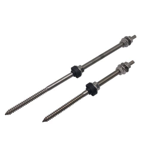
Structural choices interact with wind performance. The aluminium and galvanised steel structures described in Super Solar's solar panel ground mounting systems and its pile foundation family are configured for defined load cases, with components pre-cut and pre-drilled so that the assembled geometry matches the analysed geometry. That last point matters in high wind, since a structure assembled with different bolt positions or missing fixings does not behave like the one that was analysed. It is also worth confirming that the components delivered to site match the analysed configuration, because a missing splice or a substituted clamp changes the structural behaviour the calculation assumed.
The deliverable of a high-wind design is a calculation package with a clearly stated basis. It should identify the standard and edition, the site wind speed and return period, the exposure and topographic factors, the load combinations, the assumed material properties, the corrosion allowance, the foundation capacity and the component capacities against the governing effects. Where assumptions were made because data was unavailable, they should be listed with their sensitivity noted. A supplier who can produce this package is doing engineering; a supplier who cannot is providing a drawing.
Test evidence is valuable, but its scope is narrow. A test on a specimen demonstrates behaviour under the specific conditions applied to that specimen: the same geometry, material, connections and loading arrangement. It does not automatically transfer to a different configuration, a different foundation or a site with different pressures. When reviewing test documentation, identify what was tested, by what method, to what standard and with what result, then determine whether the project configuration is covered. Claims of testing that cannot be matched to the project's geometry should be treated as marketing rather than evidence.
Verification continues on site. Installation records should show that each support was installed to the specified depth or embedment, that fixings were torqued to specification, that clamp positions match the module manufacturer's permitted zones, and that perimeter zones received the tighter spacing the design requires. As-built documentation should capture any deviation, because a design that presumes a specific embedment is only valid if the embedment was achieved. Handover should include the calculation package, the installation records and the maintenance schedule for inspection of connections. The handover pack should also state the inspection interval for connections, since the first years of operation are when loose fasteners are most likely to appear.
High-wind sites need a real inspection regime rather than a nominal one. The most useful checks are also the simplest: looking for loosened clamps, displaced modules, distorted components and evidence of water ingress or corrosion at fasteners. Inspections are best scheduled after the first significant wind season and after any exceptional event, because that is when latent weaknesses reveal themselves. Recording findings over time turns maintenance from a cost into a diagnostic tool. Where high wind is combined with a corrosive environment, inspections should examine fasteners as closely as the structure, since corrosion can reduce a connection's capacity before any visible distortion appears.
Determine what the number represents before comparing it with anything. A quote referring to a site wind speed, a design wind speed and a tested wind speed are three different quantities, and they cannot be compared directly. Ask for the standard and edition used, the return period, the reference height, the exposure category, and the load factors applied, then check that the calculation uses the site's own wind data rather than a regional default. A quotation that cannot supply those parameters has not demonstrated anything about your project.
It helps, but only in combination with the other variables. A stronger rail is useless if the foundation pulls out, and a heavier foundation is useless if the module clamps are overloaded. High-wind performance comes from a balanced design in which foundation, support, rail, clamps and module frame are all adequate for the same governing load case. It also comes from configuration choices such as tilt angle, row spacing and perimeter reinforcement, which reduce the demand rather than only resisting it. The most effective interventions are often those that reduce demand, such as lowering the tilt or adjusting the layout, because they improve every component in the load path at once.
Often yes. Wind pressures are typically higher at the perimeter, the corners and the ends of rows, which raises uplift demand in those areas. The response may be tighter support spacing, deeper embedment, heavier foundation or additional restraint, and on some projects a perimeter that is deliberately treated as a separate design case. Even where the same components are used throughout, the spacing and embedment can differ by zone, and the drawings should show that zoning clearly so installation teams can follow it. Where the same spacing is used throughout for simplicity, that decision should be recorded, because it usually means the perimeter carries less margin than the analysis assumed.
Focus on the connections that wind can loosen and the components wind can displace. Inspect clamp tightness and clamp position on the module frames, check bolted connections at rail and support interfaces, look for movement at rails and splices, and examine fasteners for corrosion or elongation. Schedule inspections after the first wind season and after any exceptional event, and keep a record so that trends become visible. Re-torquing to specification is a routine task, but only if the specified values are known and recorded, which is one reason a solar ground mount high wind design should be handed over with its connection details documented.
Total word count: 2,481 words
 Hot News
2025-11-03
2025-10-22
2025-01-24
2024-06-12
2024-06-12