 EN

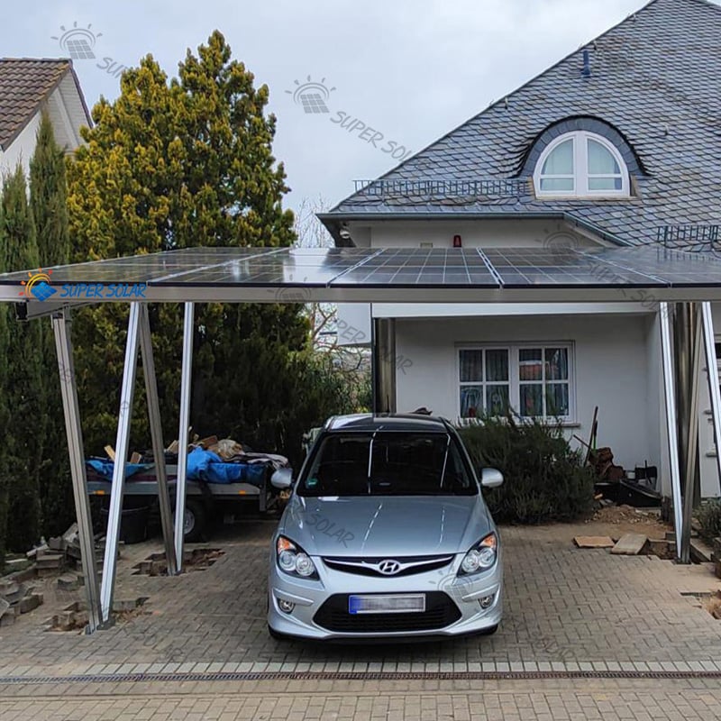

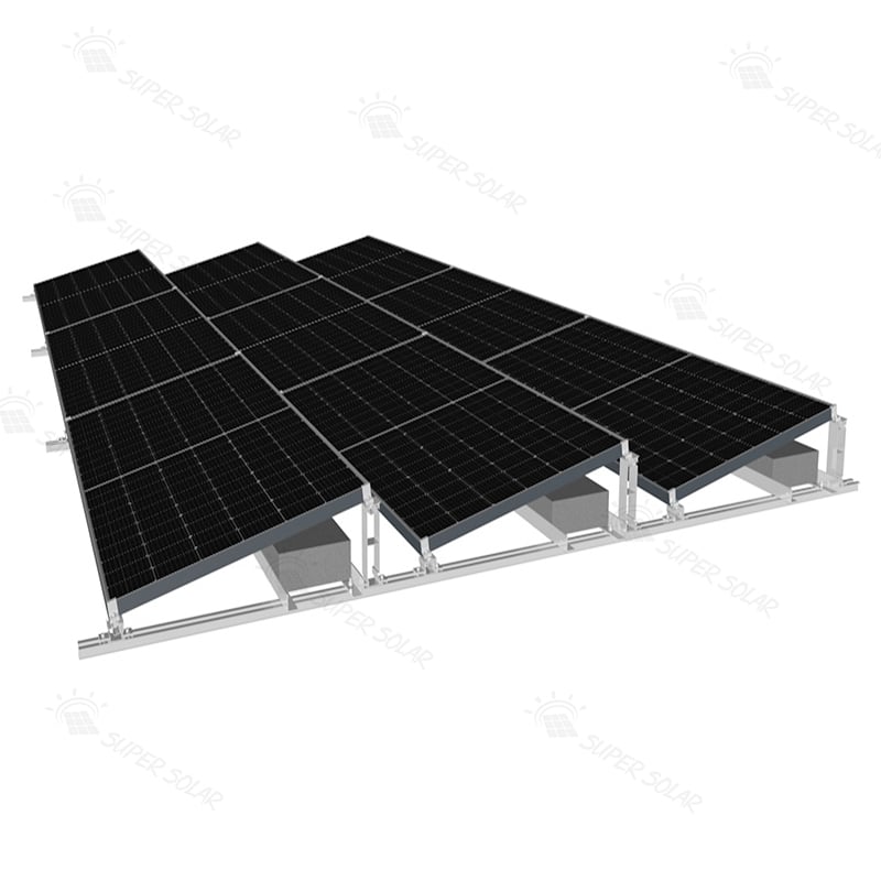
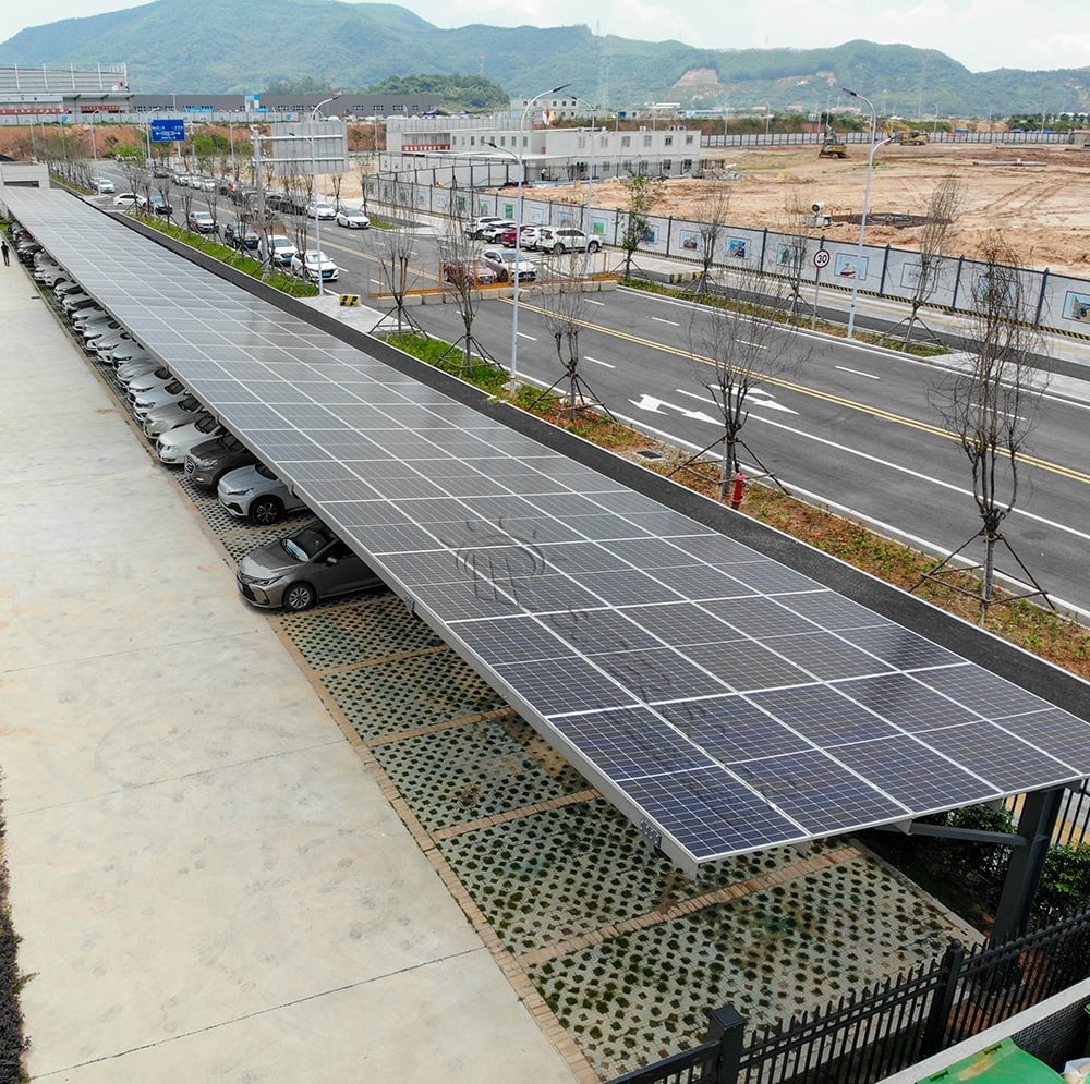

On a ground-mounted solar project, the visible engineering conversation tends to focus on the racking structure: tilt angle, module layout, row spacing, steel grade. The foundation receives less attention in meetings and more attention in the ground. That ratio is backwards. A ground mounted solar panel foundations decision determines whether the array can be built on schedule, whether the structure holds its geometry for twenty-five years, and how much of the project budget ends up in civil works. It is also the part of the project most difficult to change later, because a foundation that underperforms cannot simply be respecified at the commissioning stage.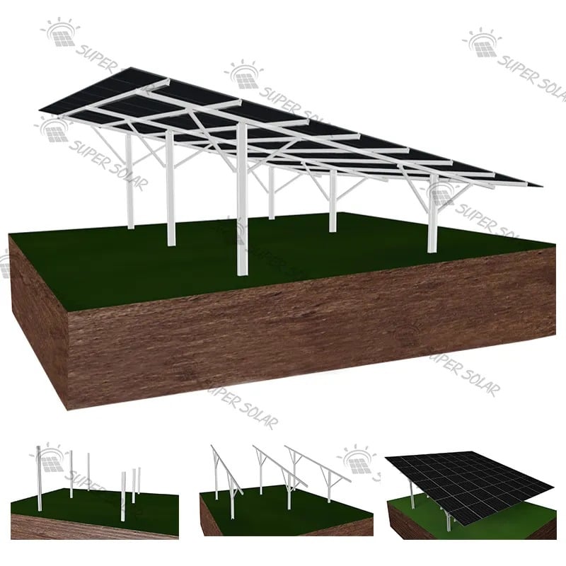
The reason foundations resist standardisation is that the ground is the variable. Two sites a short distance apart can present completely different soil profiles, water tables and bearing capacities, which is why the same racking product may be installed on driven piles at one project and on a concrete pad at another. Foundation selection is therefore driven by geotechnical data, structural loads, corrosion environment and local regulation, in that order, and the racking supplier's role is to design the structure to suit the foundation rather than to prescribe the foundation in isolation. The sections below compare the three mainstream families and identify the checks that should be completed before any option for ground mounted solar panel foundations is committed to a programme.
A driven or statically pressed pile is installed by displacing or pressing soil aside rather than by excavating, which makes it fast, clean and largely weather-independent. Capacity comes from a combination of skin friction along the shaft and end bearing at the toe, and the achievable capacity therefore depends strongly on soil type and density. In granular soils the installation process can increase local density and improve performance; in soft cohesive soils the pile relies mainly on shaft friction and may need more depth. Piles suit open terrain with reasonable access, and they leave a small surface footprint, which makes them popular for utility-scale arrays where hundreds or thousands of supports are required. At that scale, driven piles are usually the most economical form of ground mounted solar panel foundations because the installation cost is spread across a very large number of positions.
A ground screw is essentially a steel shaft with a helical blade that is rotated into the ground, developing capacity through the blade bearing on soil and through shaft friction. Installation requires no excavation and no concrete, and the connection to the structure above is usually a simple flange or bracket. Ground screws are an excellent fit for modular and phased projects because they can be installed and loaded quickly, and they suit sites where concrete delivery would be difficult. Their limits are equally clear: dense gravels, shallow rock and soils containing large obstructions can prevent installation or reduce capacity, and in aggressive soils the shaft and blade require a corrosion protection strategy appropriate to the design life.
Concrete foundations cover a broad family, from cast-in-place pad footings and strip footings to precast blocks used as ballast weight. They are heavy, tolerant of difficult bearing conditions when designed correctly, and familiar to local contractors in most markets. A concrete pad allows load to be spread over a large area, which is useful where bearing pressure is the governing limit, and ballast offers a way to build where excavation or penetration is restricted. The trade-offs are time and logistics: concrete requires formwork, reinforcement, curing and often water, all of which depend on weather and site access, and it adds substantial transport weight to the project. Ballast also needs to be verified against uplift, because its capacity comes from mass rather than from ground anchorage.
Foundation and structure must be designed as one system. The mount connects to the pile, screw or pad through a defined interface, and the structure has to accommodate the tolerance of the foundation as well as its stiffness. Super Solar's solar panel ground mounting systems are developed with the foundation interface as part of the design, and the U-type and C-type pile configuration described in the pile foundation product family illustrates how a single support column with pre-cut, pre-drilled components can reduce both fastener count and erection time once the foundation has been established.
The foundation design starts with boreholes or test pits sufficient to characterise the site, not with a single sample at the entrance gate. Soil classification, relative density, moisture content, plasticity and the presence of fill material all affect the achievable capacity, and fill or previously worked ground deserves particular scrutiny because its behaviour is unpredictable. Where the site is large, the investigation should be distributed across the area and targeted at the locations of the array's most heavily loaded supports, including the perimeter rows where wind uplift is greatest. Skipping that distribution to save investigation cost is a false economy, because ground mounted solar panel foundations must be adequate at the weakest location on the site rather than at the average one.
Two conditions change the design most sharply. Shallow rock or a hard layer causes refusal during pile driving or screw installation, which can stop a programme entirely if it has not been anticipated. Groundwater limits excavation, complicates concrete works and can require dewatering. Both should be identified at investigation stage and quantified, including the depth at which refusal occurred in trial installations and the seasonal high water level rather than the level observed on a single visit. Recording the season and the method used to measure groundwater makes the data usable, because a level measured in a dry month is not the level a foundation design should assume.
Ground-mounted foundations are partly buried, which places them in a corrosion environment that is more severe than the above-ground structure. Soil resistivity, pH, chlorides, sulphates and stray current all influence how quickly a steel element degrades, and the requirement is normally expressed as a thickness allowance, a coating system or a material substitution matched to the intended service life. Because the buried portion cannot be inspected or maintained, the corrosion allowance has to be correct at the outset. In coastal and saline sites, this frequently governs the choice of material as much as structural load does.
Access determines which installation equipment can reach the site and how quickly works can progress. A piling rig needs a route and a working platform; a ground screw machine needs less; concrete needs a delivery route that remains passable in wet weather. Seasonal constraints then decide the programme: a site that is workable in a dry season may be inaccessible in a wet one, and this can shift the economic comparison between foundations by a wide margin. Where access is seasonal, it is worth confirming that the on-site storage area can hold the materials required for a full working season, because a stalled delivery becomes a stalled foundation programme.
Wind uplift typically governs ground-mounted arrays, particularly on perimeter rows and at the ends of rows, and it acts to pull the foundation out of the ground. Compression governs where snow accumulates or where the structure is heavy. Lateral load arises from wind pressure on the array and from the tilt geometry, and it is often the least well considered of the three. Foundation capacity must be checked against all three simultaneously, because a foundation adequate in compression can still fail in uplift or translate laterally.
Because theoretical capacity in soil carries uncertainty, many projects verify it by testing. A pull-out test measures the resistance of an actual installed pile or screw to extraction, and a lateral test measures resistance to horizontal movement. Testing on a representative sample, at the same installation method and depth used in production, provides a defensible basis for design and can allow an optimisation that analysis alone would not support. Test results should be recorded with their location, installation data and soil description so that they can be linked back to the design assumptions.
Foundation design must satisfy the governing local building code and any project-specific requirement imposed by the owner, lender or insurer. The documentation set normally includes the geotechnical report, the foundation design calculation, the test results where available, the structural design of the racking, and drawings showing the interface between the two. Where a code requires a specific factor of safety or a specific load combination, that requirement should be stated in the design basis so the supplier can design to it from the beginning rather than after the fact.
Finally, the foundation and the racking must be checked together for stiffness, because a foundation that is structurally adequate can still allow enough movement to affect module alignment or to fatigue connections over time. This is particularly relevant on long rows and on tracker structures, where small movements accumulate. Confirming the interface stiffness at design stage is far cheaper than discovering it during commissioning. On tracker structures the interface becomes more sensitive again, because the drive and control architecture assumes a support that holds its position within a defined tolerance for decades.
Foundation cost comparisons only make sense on a total installed cost basis. Material cost per unit is only one element; the comparison should include installation equipment and crew, site preparation, concrete supply and curing, spoil removal, reinstatement, weather downtime and the effect of each option on the overall programme. A foundation with a higher unit price may be cheaper overall if it installs faster and allows the array to be commissioned earlier, and the reverse is equally true on small, restricted sites. Where two options differ mainly in programme, the earlier commissioning date can be valued directly as additional generation rather than treated as a soft benefit.
Driven and screwed foundations are comparatively weather-insensitive and can proceed in cold conditions where concrete cannot be placed. Concrete works, by contrast, are sensitive to temperature, rainfall and curing time, and they typically require a longer lead-in. On projects with a fixed completion date, weather sensitivity can outweigh a modest difference in unit cost, and it should be quantified as a programme risk rather than absorbed silently. Recording the weather assumptions alongside the cost comparison makes the programme risk visible to the project team rather than buried in a contractor's contingency.
Work through the decisions in order. Establish the geotechnical profile, refusal depths and groundwater conditions. Establish the design wind, snow and lateral loads with the governing code. Confirm access and seasonal constraints. Then compare foundations on total installed cost and programme risk, verify the chosen option by testing where uncertainty is material, and finalise the racking interface. Reversing that order produces designs that are theoretically elegant and practically unbuildable. Documenting that sequence in the design file is what allows the foundation decision to be audited later, when the site looks different from the way it looked at tender.
Only where the geotechnical conditions and the design loads are genuinely comparable. Foundation capacity depends on the soil profile, the refusal depth, the groundwater level and the corrosion environment, and it is also a function of the wind and snow loads at the site. A design proven on one project is a useful starting point and a poor substitute for site data. The efficient approach is to standardise the interface and the installation method while recalculating capacity for each site, which keeps the structure and the components common without pretending that the ground is. That discipline is what allows a supplier's ground mounted solar panel foundations range to be reused across projects while the design remains site-specific.
Ground screws tend to be preferable where access is restricted, where the project is modular or phased, where concrete delivery is impractical, or where installation noise and vibration must be limited. They suit sites with reasonably consistent, penetrable soils and no shallow obstructions. Driven or pressed piles become more attractive on large utility-scale arrays where high production rates matter, where soils are dense but penetrable, and where the racking design assumes pile deflections typical of driven installation. The decisive factors are usually the soil profile and the required installation rate.
Enough testing to reduce the governing uncertainty below the margin the design already carries. A single well-documented pull-out and lateral test at a representative location, installed by the production method and to the production depth, is far more valuable than several tests installed with a different rig or to a different depth. Where the site is heterogeneous, distribute tests across the distinct soil zones identified in the investigation. Record installation torque or driving resistance alongside the test result, because that data lets you interpret production installation records later.
The supplier needs the geotechnical summary including soil classification, refusal depth and groundwater level, the design wind and snow loads with the governing standard, the corrosion environment and required service life, the foundation type and its top-level interface detail, the site access conditions and the intended installation method. With that input the racking design can be matched to the foundation rather than designed in isolation, and the interface tolerances can be agreed before fabrication starts.
 Hot News
2025-11-03
2025-10-22
2025-01-24
2024-06-12
2024-06-12