 EN
EN



A request for quotation that takes ten minutes to write usually produces a price that takes ten days to correct. When a supplier receives a request that names a roof type, a module count and a delivery port but omits the roof profile, the purlin spacing, the design wind load and the module frame thickness, the only honest response is either a list of questions or a price built on assumptions. If the supplier prices on assumptions, the quotation becomes a placeholder, and every subsequent clarification changes the material list, the packing and sometimes the whole system type. The cost of that cycle lands on the installer through delayed programmes and revised budgets.
A complete solar mounting system supplier RFQ is not a bureaucratic exercise in writing requirements down. It is the mechanism by which design responsibility is transferred correctly. When an installer supplies the roof profile, the structural information, the loads and the module data, the supplier can design the mounting system and take responsibility for the components meeting the stated conditions. When the installer omits them, the supplier can only quote components, and the design responsibility stays where it started. The checklist below follows the order in which a supplier actually needs the information, and it doubles as an internal file structure for the installer's own records.
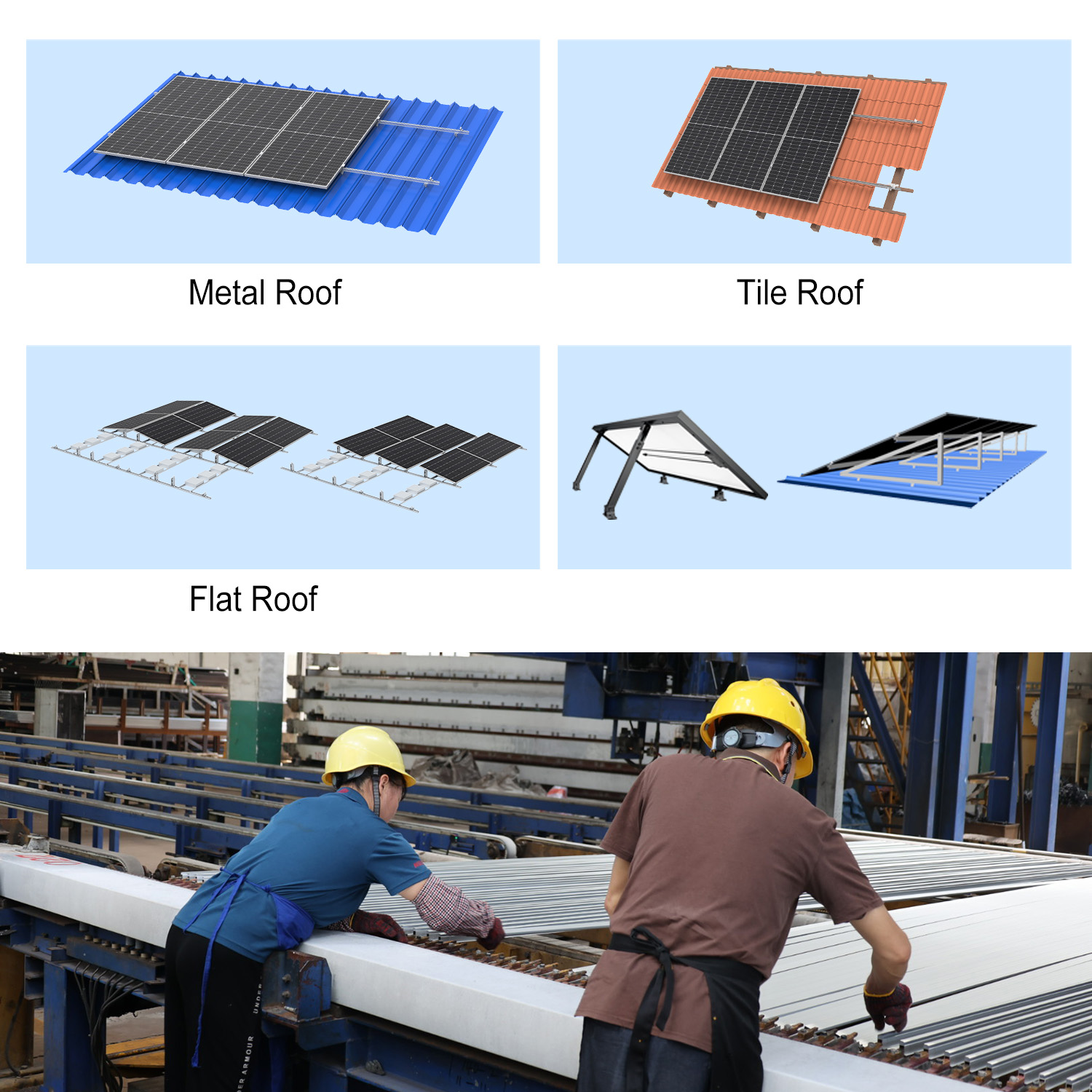
Identify the roof covering family first, because it determines the attachment family. Tile, slate, trapezoidal metal sheet, corrugated sheet, standing seam metal, and flat membrane roofs each correspond to a different mounting approach, and the supplier needs to know which one applies. Then describe the structure beneath: rafter or purlin material, section, spacing and condition, and whether the roof is new or being refurbished. On older buildings, note any evidence of deterioration, previous repairs or non-standard construction, because a mounting design assumes a substrate that can carry the load. Add photographs of a typical roof area and of any difficult detail such as a ridge, valley, penetration or plant area.
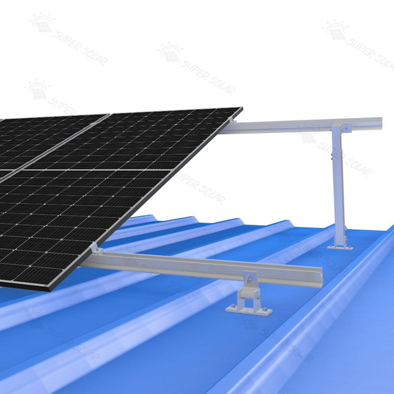
Provide the covering details that determine component geometry. On tile roofs, that means the tile type and profile, the tile thickness and the pitch. On metal roofs, it means the sheet profile and thickness, the rib or seam geometry, the purlin spacing and the finish of the sheet. On flat roofs, it means the membrane type, the insulation build-up and whether penetration is permitted at all. Where dimensions are uncertain, include a photograph with a tape measure in frame, which is often faster and more accurate than a description. Super Solar's overview of solar mounting system components explains how these components fit together for each roof type, which is useful context when compiling the first page of a specification.
State the project location, the elevation if relevant, and the surrounding environment: open country, coastal, urban, industrial or agricultural. These determine the corrosion exposure and the wind exposure. Then state the design wind and snow loads with the governing standard and edition, or ask the supplier to derive them if that is part of the scope. Include any requirement imposed by the owner, the authority or the insurer, such as a specific return period or an approval document format. Lifecycle requirements belong here too: expected service life, maintenance regime and any warranty expectations the client has stated. A solar mounting system supplier RFQ that omits the site's exposure class will produce a quotation carrying an unstated corrosion assumption.
The mounting system is designed around the module, so the supplier needs the module datasheet rather than the nominal wattage. Module length, width and depth, frame thickness and profile, and the manufacturer's permitted clamping zones all affect the rail spacing, the clamp selection and the rail position relative to the module edge. Where more than one module type is used, list them all, because a design that suits the smaller frame may not suit the larger. Bifacial and large-format modules sometimes carry stricter clamping requirements and should be identified as such rather than grouped with standard modules.
Describe the array as it will actually be built: the number of modules, the orientation in portrait or landscape, the number of rows and columns, the number of separate sub-arrays and their positions on the roof, and the intended rail direction. Include the tilt if the array is not parallel to the roof surface, and the row spacing where the array is on a flat roof. Note any obstructions that the array must work around, including chimneys, vents, roof lights, air conditioning plant, access routes and the positions of any existing penetrations.
Confirm the design wind and snow loads and the standard they are taken from, then state whether the supplier is expected to perform the structural calculation or to design to loads supplied by the installer's engineer. State the required material grade and finish where the site is coastal or otherwise corrosive, and note any requirement for non-penetrating fixing. If the project requires specific documentation such as a structural report, shop drawings or material certificates, list it here rather than discovering the requirement later. Where the loads are still being derived, ask for the quotation to be flagged as provisional so that the commercial position is clear to everyone involved.
Where the roof has pre-existing penetrations, anchors or equipment, list them, because they constrain the mounting layout and can conflict with the rail grid. Confirm which structural members can be drilled and which cannot, and whether any fire separation or waterproofing detail limits the number or the position of penetrations. On refurbishment projects, note the condition of any previous mounting system being removed, since reusing penetrations is sometimes possible and sometimes inadvisable. Where an existing penetration must be reused, ask the supplier to confirm that the surrounding sheet can still support the intended fixing rather than assuming that it can.
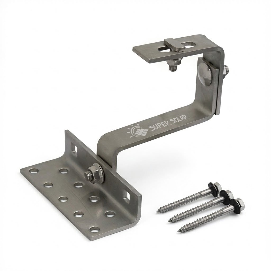
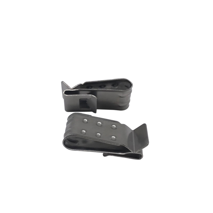
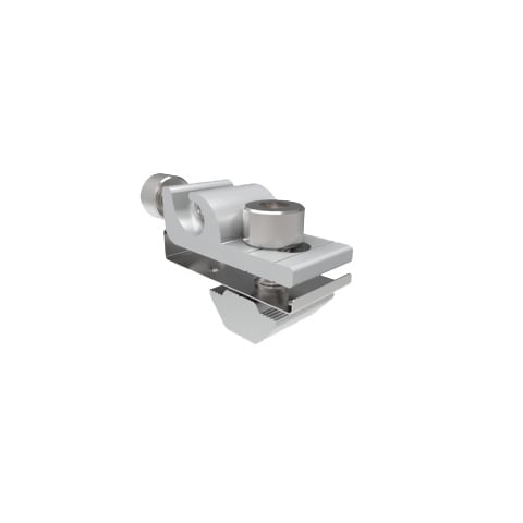
Define the scope precisely. Roof mounting system components typically include the roof attachment, the mounting rails, rail splices, mid clamps, end clamps and grounding accessories, and they may also include flashing components, cable management and dedicated standing seam clamps. State which of these the supplier is quoting, and which the installer will source locally. Ambiguity here is one of the most common causes of a short shipment, particularly for small but essential items such as rail splices and grounding clips, which are easy to omit from a component list and impossible to omit from an installation.
State the required material grade for each component family: for example aluminium alloy for rails and brackets, stainless steel for roof hooks and fasteners, and a defined coating system where steel is used. State the anodising thickness or the coating class where relevant, and confirm that fasteners match the corrosion requirement rather than defaulting to a standard grade. On coastal, industrial or agricultural sites, this section should be explicit, because the difference between adequate and inadequate roof mounting system components is often a single grade or a single coating mass.
List the standards the design must satisfy, and the certifications and test documentation the project requires. Then specify the drawings the supplier should produce: a general arrangement showing the array layout, a component location drawing, section details at each distinct roof condition, and installation instructions. Agreeing the drawing list at RFQ stage avoids the situation where a supplier provides a neat layout plan and the installer discovers there is no detail for the ridge, the valley or the flashings. It is also worth confirming the language and units of the drawings, since a detail drawing that cannot be read on site is effectively not issued.
A responsive quotation includes more than a price. Look for a system proposal naming the specific components and their quantities, a drawing or layout sketch, the load basis used, the material and finish specification, the packing and shipping configuration, and the assumptions the price depends on. Super Solar supplies drawings, load information, samples and technical documentation alongside its quotations and offers free project design and structural calculation, which is the level of detail that makes an installer's own submission straightforward. Where any of those items is missing, the quotation should be treated as incomplete rather than accepted and clarified later on site.
Give the module count and the expected kW capacity, but also state whether the order covers the whole project or one phase, and whether a follow-on order is likely. Note the required quantity of spare components, particularly clamps, bolts and flashing items, and whether the installer intends to hold stock for maintenance. Phased projects should state the delivery sequence, because a partial shipment that omits the components needed for the first phase delays the start of work regardless of how complete the later phases are. Where the project is phased, the spare allowance should be set per phase as well as in total, since the components needed for maintenance are not necessarily delivered with the final shipment.
State the delivery point, the required shipping term, the packaging expectations and any labelling requirements, along with any restriction on pallet dimensions or container loading. On long rails, the packing method materially affects handling and transport cost, so it is worth confirming how extrusions will be protected and supported. Where the installer's own brand appears on the packaging, raise it at RFQ stage rather than after the order. On long extrusions the packing method also determines whether the rail arrives straight, so it is worth asking how the lengths will be supported inside the pallet.
For a first order, request a sample of the key attachment component and any component whose fit is uncertain. Sample approval should cover fit to the roof profile or tile, the quality of the sealing element, hole alignment and finish. Agree the approval cycle in advance, including who reviews the drawings and how long that takes, because the critical path on a mounting package is often approval rather than production. Where a project has a fixed start date, the approval cycle usually sits on the critical path, so agreeing who reviews what and by when is a schedule decision as much as a technical one.
Turn the checklist above into a one-page form that the project team completes before sending any enquiry, and keep it with the project file. The most frequently omitted items are the purlin or rafter spacing, the module frame thickness, the design wind and snow loads with their standard, the roof profile detail, the non-penetrating requirement and the specific scope boundary for accessories. Each of those omissions causes either a revised quotation or a site problem, and each takes only a moment to record. Used consistently, the form converts a solar mounting system supplier RFQ from correspondence into a controlled document.
At minimum a supplier needs the roof type and profile, the substrate and its spacing, the module datasheet, the array layout, the design wind and snow loads with the governing standard, the site location and corrosion environment, the required material and finish, the delivery point and the order quantity. With those inputs a supplier can propose a specific system rather than a component list. Without them, a solar mounting system supplier RFQ can only produce a contingent price that should be treated as indicative rather than as a basis for ordering.
Either arrangement can work, provided it is agreed before the quotation is issued. If the installer's engineer supplies the design loads and the supplier designs to them, the division of responsibility is clear and the supplier's scope is well defined. If the supplier is asked to derive the loads, that should be stated in the RFQ along with the standard to be applied and the documentation required. The problem arises when neither party owns the calculation, which leaves the mounting system without a load basis at all.
Enough to cover breakage, loss and minor variations during installation, plus a small maintenance allowance for the first years of operation. The appropriate allowance depends on the component and on the site: small fasteners and flashing items are cheap to over-order and disruptive to short-order, while long rails are the opposite. A useful approach is to quantify spares as a percentage of the component count, with a higher allowance for fragile or easily lost items, and to keep the record so the next project can be calibrated against actual consumption.
Because it determines which clamps will fit and where they may be positioned. Clamps are produced for specific frame thickness ranges, and a clamp intended for one frame depth may not grip another correctly, which affects both the mechanical fixing and the electrical grounding path. The module manufacturer's installation instructions also define permitted clamping zones along the frame, and those zones determine how far the rail can sit from the module edge. A specification that ignores frame thickness can be structurally adequate for the rail and still be wrong for the module.
 Hot News
2025-11-03
2025-10-22
2025-01-24
2024-06-12
2024-06-12