 EN

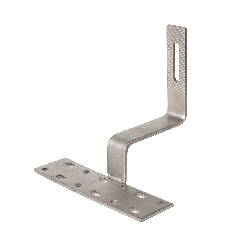
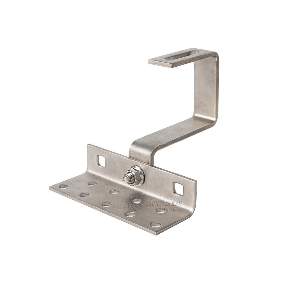

Solar mounting structures are held in place by one of two principles. Either the structure is anchored into the ground and resists load through the strength of that anchorage, or it is loaded with mass and resists uplift through weight. Pile-driven systems belong to the first family; ballasted systems belong to the second. Both are legitimate, both are widely used, and both are frequently misapplied because the word ballast is used loosely to describe several different things. Clarifying what is meant by a ballast system ground mount before comparing options is the single most useful step a project team can take, because the comparison only makes sense once the alternatives have been defined precisely.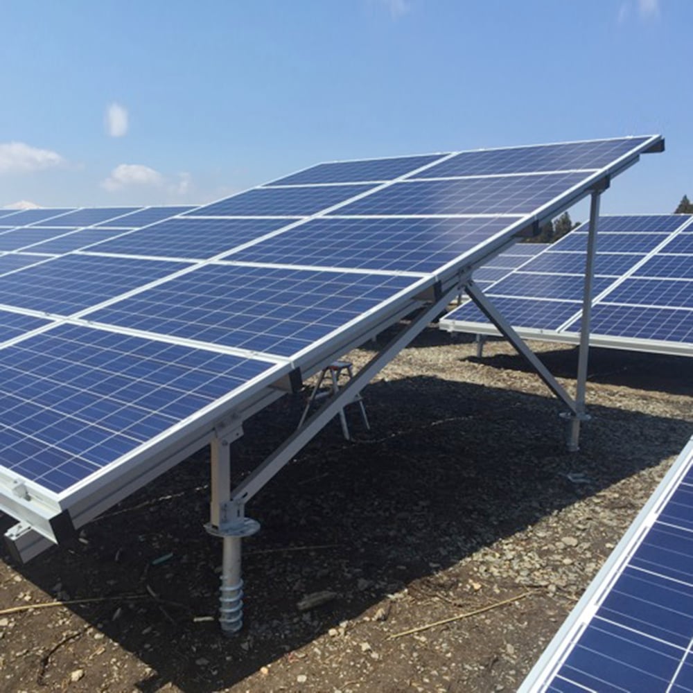
The confusion arises because ballast appears in more than one context. On flat commercial roofs, ballasted frames and trays sit on the membrane and rely on weights, usually concrete blocks, to hold the array down against wind. On the ground, ballast may be used as an alternative to driven foundations where penetration is restricted or ground conditions prevent it. And in the tracker world, ballast is occasionally proposed for sensitive sites. Each of these is a distinct engineering solution with different verification requirements, and treating them as interchangeable leads to designs that are either over-conservative or unsafe. The sections below separate the families, set out the requirements of each, and then match them to site conditions so that a ballast system ground mount is chosen for the right reasons rather than by default.
A rooftop ballasted system places the mounting frame or tray directly on the roof surface and holds it down with weights. No roof penetration occurs, which preserves the waterproofing layer and is often the decisive advantage on membrane roofs or commercial buildings where the roof warranty prohibits penetration. Typical tilt angles on flat roofs are deliberately shallow, commonly in the range of five to fifteen degrees, because steeper angles increase uplift substantially. The governing checks are the roof's load-bearing capacity, the uplift resistance of the ballast, and the avoidance of any detail that could puncture or abrade the membrane beneath the frame.
On the ground, a ballasted approach replaces penetration with mass and bearing. The structure sits on the surface, often on a prepared pad or a spread footing, and stability comes from weight combined with bearing pressure on the material below. This family is relevant where the ground is too hard to penetrate, where buried services or archaeology make drilling unacceptable, or where the installation must be reversible. Because the array behaves like a wing, uplift is again the governing case, and it has to be resisted entirely by weight and anchorage. Bearing pressure on the subgrade must be checked separately, because a pad concentrates a considerable load over a small area. Those two checks together define whether a ballast system ground mount is viable on a given site, and neither can be answered without the site's own wind data and subgrade information.
Ballast is a strong answer to a specific problem: how to install an array where penetration is prohibited or impractical. It is a poor answer to a different problem: how to carry very high uplift on an exposed site without a large increase in material and transport cost. Ballast capacity is proportional to weight, so increasing the wind rating means increasing the mass that has to be trucked in, laid, and in the case of rooftops, supported by the building structure. At some point the mass required becomes impractical, and an anchored solution becomes the better answer. Knowing that threshold in advance prevents a design cycle that ends in an unbuildable solution.
A driven or pressed pile develops capacity through skin friction along its shaft and bearing at its toe, so its performance is a direct function of the soil profile and the achieved embedment. Granular soils usually give good friction capacity and can increase in density during driving, while soft cohesive soils depend more on shaft adhesion and often need greater depth. The required depth is derived from the governing load case, which on exposed sites is usually uplift, and it must be verified by geotechnical investigation and, where uncertainty is material, by on-site pull-out testing. Reducing embedment to suit a shorter pile rather than deriving the pile length from the load is a design error that surfaces in the first storm, and it is the main reason a piled solution can appear cheaper than a ballast system ground mount at tender and more expensive after the first winter.
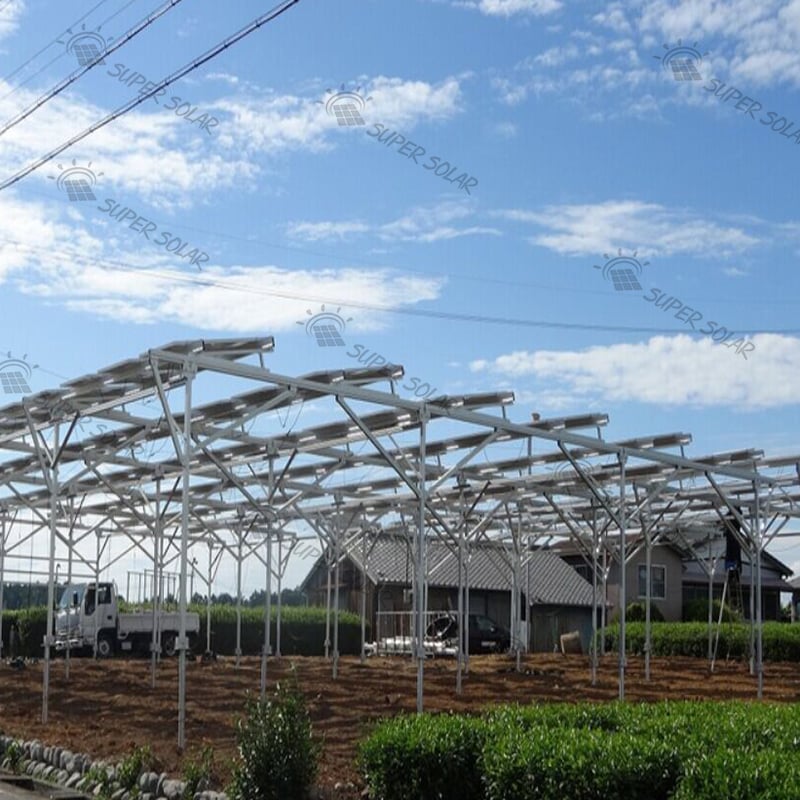
Pile installation is fast on suitable ground and can proceed in conditions that would stop concrete works. The method matters for the structure as well as the programme, because driving can displace soil and move previously installed piles, so installation sequence and survey control become part of quality assurance. A common arrangement on utility-scale projects is a single support column per position with pre-cut, pre-drilled components, which reduces fastener count and speeds erection once the pile is in the ground. The components and their interfaces are described in Super Solar's pile foundation product family, which is designed around exactly this principle of a simple support with pre-assembled connections.
The buried portion of a pile is the part that cannot be inspected or maintained, so its corrosion allowance must be correct from the start. Soil resistivity, pH, chlorides, sulphates and stray currents all affect the rate of deterioration, and coastal or saline sites require particular care. Protective approaches include hot-dip galvanising to a specified coating mass, alternative metallic coatings, material grade selection and, where necessary, a thicker section used as a corrosion allowance. The service life requirement should be stated explicitly, because the same site can support quite different corrosion strategies at different design lives.
Piles require penetrable ground. Shallow rock, dense gravel, buried obstructions and sites with extensive underground infrastructure can prevent installation or make it unreliable. Where the ground refuses the pile, or where the achieved embedment cannot meet the load case, the correct response is a different foundation rather than an optimistic reduction of the requirement. Pilot installation during the investigation phase is the most reliable way to discover this before the programme depends on it. Recording the refusal depth from a pilot installation gives the next phase of the project a starting point instead of another full investigation.
The decision usually follows from a small number of site facts. If penetration is prohibited, ballast or another non-penetrating solution is indicated. If the ground refuses piles, the choice is between pre-drilling, rock anchoring, concrete and ballast. If the site is heavily exposed to wind, the mass required by ballast may become impractical and an anchored solution becomes preferable. If access is difficult and concrete delivery impossible, ground screws or driven piles gain an advantage. If the roof or ground surface cannot take concentrated load, a spread or ballasted arrangement is needed. Establishing these facts first collapses a long option list into two or three real candidates, and it makes the eventual ballast system ground mount decision defensible on evidence rather than on preference.
Whatever the family, the same set of load cases has to be satisfied: uplift from wind, downward load from the structure and any snow, and lateral load from wind pressure and tilt geometry. Ballast resists uplift through mass, so the calculation is essentially a balance between weight and lift, and it is sensitive to the local pressure coefficients at the array perimeter. Anchored systems resist uplift through the anchorage, and their calculation depends on soil capacity and embedment. Bearing pressure applies to both, and it is the check that most often constrains a design on soft ground or on a lightweight roof.
Cost comparisons should be made on total installed cost including transport and site works. Ballast is material-heavy, so freight dominates, and on rooftops the weight also has to be carried by the building structure and moved by crane or hoist. Anchored foundations are material-light but equipment-heavy, and their cost depends on access, ground conditions and production rate. Weather sensitivity differs as well: driven and screwed foundations proceed in most conditions, while concrete needs curing time and favourable temperatures. Weighing these factors correctly usually matters more than the unit price of the components.
Two further considerations sometimes decide the matter. A ballasted or non-penetrating solution is reversible, which can be valuable on leased land, on sites with future development plans, or where the installation must be removed at the end of an agreement. An anchored solution is more permanent but generally provides higher capacity per unit of material. Where the site may later be redeveloped, reversibility can outweigh a modest cost penalty, and it is worth stating that priority explicitly in the brief. It is worth confirming at the outset who is responsible for removing the installation, because that obligation affects both the design and the residual value of the asset.
Before comparing options, assemble the geotechnical profile with soil descriptions and depths, the refusal depth and behaviour observed with the production installation method, the groundwater level and season of measurement, the corrosion environment and the required service life. Add the access conditions, the available working platform, and any restriction on penetration. The comparison cannot be concluded honestly without these inputs, and obtaining them early is what makes the foundation decision a design decision rather than a reaction to site conditions. Skipping that work to shorten the tender period usually moves the same cost into the construction phase, where it is considerably harder to price.
The chosen design should be supported by a calculation package that states the standard used, the load cases and factors, the capacity of the foundation, the interface details and the corrosion strategy. Where the project requires owner, lender or authority approval, the required format should be confirmed early so the documentation is produced once rather than twice. Super Solar's ground mount solar ballast and general ground mounting system design work, together with its structural calculation support, allow the correct foundation family to be matched to a given site rather than assumed.
Confirm whether penetration is permitted. Confirm whether the ground accepts penetration and to what depth. Establish the governing uplift and lateral loads. Establish the bearing capacity of the supporting surface. Compare total installed cost including transport, equipment and weather downtime. Confirm the corrosion strategy against the service life. Verify the interface tolerance between foundation and structure. Agree the approval documentation format. Then pilot install one position before committing the full programme, because one installed anchor tells you more than any further desk comparison. Recording the answers alongside the chosen design turns the checklist into the audit trail that an owner or lender can review.
No, although both use weight. A rooftop ballasted system sits on an existing building and relies on the roof's structural capacity to carry the added dead load as well as the array's uplift. A ground-mounted ballasted system bears on prepared ground or a pad and depends on the subgrade's bearing capacity. The uplift checks are conceptually similar, but the supporting structure, the interface detail, the restrictions and the installation method differ substantially, and specifying one while designing the other is a real and avoidable error. A ballast system ground mount is a ground solution, and it should be designed against subgrade bearing capacity rather than against a building's structural capacity.
Neither is inherently cheaper, because cost is dominated by site-specific factors. Ballasted systems carry high transport and handling costs proportional to their mass and can require heavy lifting equipment, while anchored systems depend on installation equipment, access and ground conditions, and can be slowed dramatically by hard ground or obstructions. A fair comparison prices the complete installation including freight, site preparation, equipment, labour, weather downtime and any reinstatement obligation. The balance frequently shifts between one site and the next on the same project portfolio. Comparing the two on a per-kilowatt basis without also comparing the services each delivers tends to favour whichever option was specified first.
Yes, and this is one of the situations where a ground-mounted ballasted solution is genuinely appropriate, alongside rock anchoring and pre-drilled piles. The constraint to verify is uplift, because the mass required to resist the governing wind case may be substantial, and the bearing pressure beneath each pad must be checked against the material at the surface. Where the exposed condition is severe, the better answer may be an anchor grouted into the rock rather than weight alone. Where the required mass becomes impractical, an anchor grouted into the rock is usually a more economical answer than additional weight.
Testing is required wherever uncertainty in capacity is material to the design. For anchored foundations, pull-out testing and, where relevant, lateral load testing on production anchors installed by the production method provides direct evidence of achievable capacity and can justify an optimisation. For ballasted systems the equivalent verification is a documented uplift calculation against the governing wind case, combined with confirmation of the bearing capacity of the supporting surface. In both cases the results and the design assumptions should be recorded together so the design can be reviewed independently.
 Hot News
2025-11-03
2025-10-22
2025-01-24
2024-06-12
2024-06-12