 EN

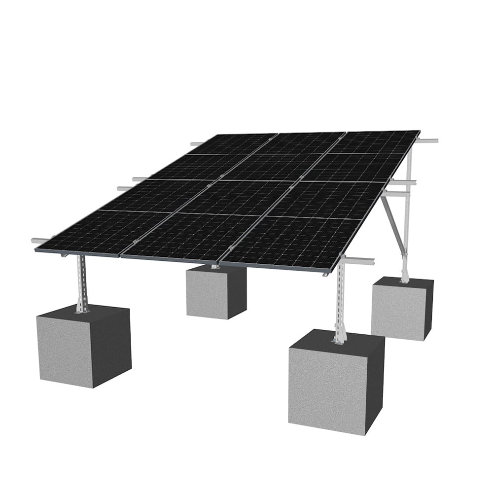
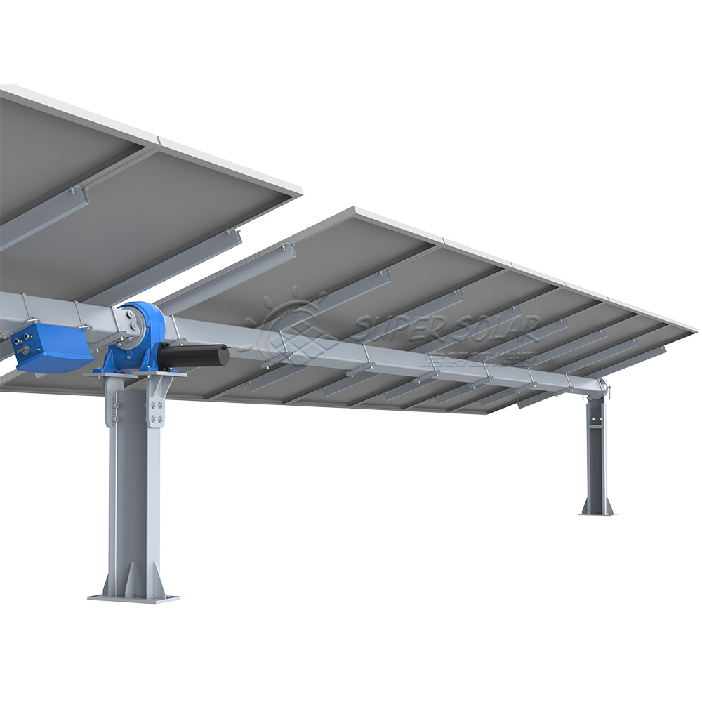
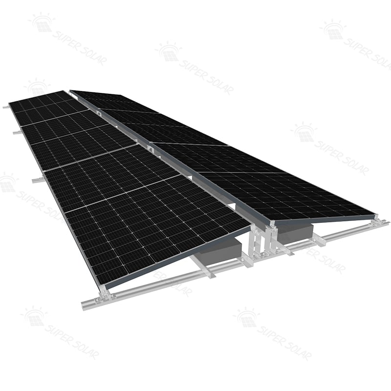

On a trapezoidal metal roof, the rail is the component that has to satisfy the most parties simultaneously. It must bolt down onto an L-foot or roof screw that reaches a purlin. It must accept mid clamps and end clamps that grip the module frame at the correct height. It must span between fixing points without deflecting beyond the design limit. It must hold those relationships through thermal cycling and decades of weather. When a designer looks for a solar rail for trapezoidal tin roof applications, the useful question is not which profile is strongest in the abstract, but which combination of profile, fixing detail and spacing satisfies all of those interfaces on this specific building.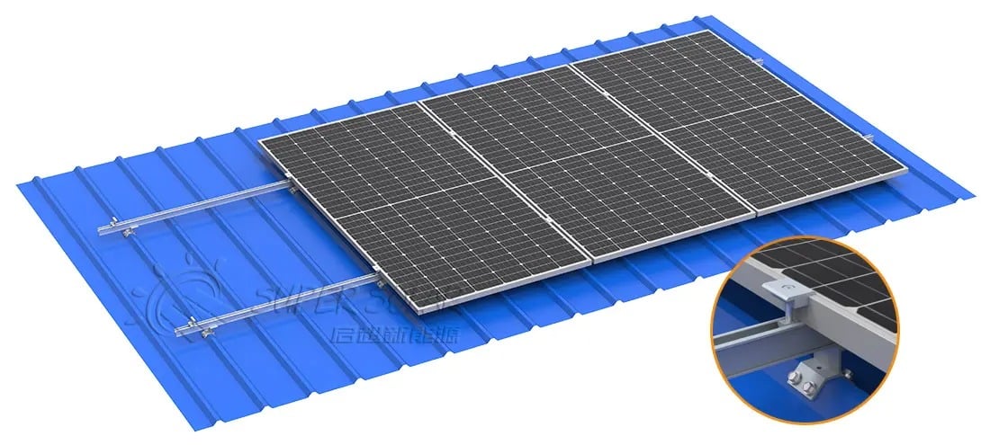
That is also why fixed universal values for rail spacing, fastener positions and maximum loads are not available, and any supplier who publishes them as a blanket rule is simplifying away the variables that matter. Spacing is a function of the module, the clamp positions, the purlin grid, the design wind and snow loads and the local code. Fastener selection depends on the sheet and the substructure. Load capacity depends on all of it. The sections below work through the interfaces in the order a designer encounters them, and identify the inputs that have to be confirmed before a spacing for a solar rail for trapezoidal tin roof application can be calculated at all.
Aluminium rails are typically extruded from 6005-T5 alloy and anodised, a grade and finish chosen for structural stiffness and corrosion resistance rather than appearance. Common sections include 40×40 mm and 40×50 mm profiles, with 50×50 mm and custom extrusions available for heavier duty. The 40×40 section is a lightweight choice for metal roof arrays with modest loads, while the 40×50 profile is a general-purpose section used across metal, tile and ground applications where more capacity or a taller stand-off is needed. T-slot and H-shaped sections appear where a particular accessory interface is required, and heavy-duty configurations are used for high-load sites. Selecting the smallest adequate section is the usual cost optimisation, provided the load case is genuinely known.
The rail must accept the clamps, and the clamps must accept the module. Frame thickness is the controlling variable: standard framed modules commonly fall in the 30 to 40 mm range and many arrays also include 45 mm frames, so a system that is quoted as compatible with 35 mm or 40 mm frames should be confirmed against the actual module datasheet rather than assumed. Above the module, the clamp height and the mid-clamp geometry set the spacing between module rows and the bearing area on the frame. Below, the rail slot or hole pattern must match the bolt or T-bolt used by the bracket. In practice, most compatibility failures on trapezoidal roofs are clamp and bolt interface problems rather than rail strength problems.
Rails rarely run the full length of a roof in one piece, so rail splices and their load transfer behaviour belong in the design. A splice is not merely an alignment device; it must carry the same bending moment and shear as the adjacent rail section, and its position relative to a fixing point affects that. T-bolt connections at bracket positions should be checked for the correct slot engagement, and accessories such as grounding clips have their own interface requirements. Where the rail also carries cable management components, that is a further interface to confirm, since clips and conduits should not compromise the structural section. Super Solar supplies its solar panel mounting rails as a range of extrusions with defined clamp compatibility, rail splices and accessory interfaces so that the whole assembly is specified together rather than piece by piece.
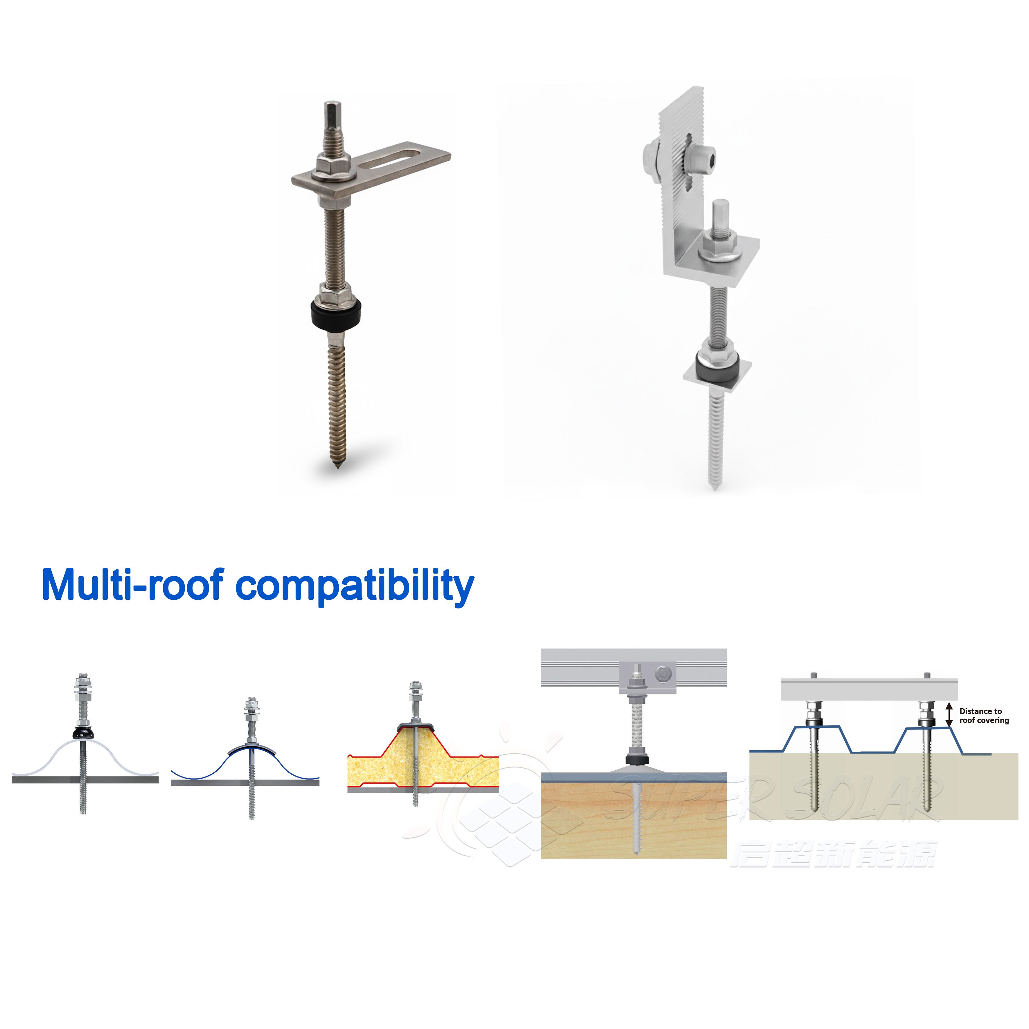
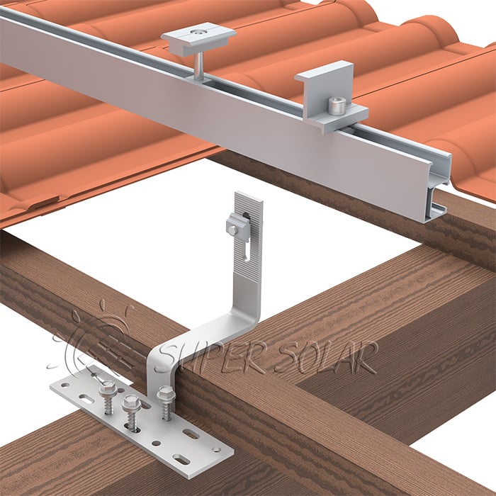
The rail normally attaches to an L-foot, a roof screw with a calotte, or a rail-mount bracket fixed to the sheet, and the fixing position must land on structure. On trapezoidal profiles this usually means the purlin, and where the purlin is not available at the required location, the options are to shift the rail spacing, add a secondary member or accept a longer span with the corresponding design penalty. Bolt orientation matters too: the connection should be loaded in the direction it was designed for, and any slotted connection used to accommodate position tolerance should still develop the required clamping force when tightened to specification. This is the detail most often left loose in drawings, yet it is the connection that determines whether a solar rail for trapezoidal tin roof installation behaves as analysed.
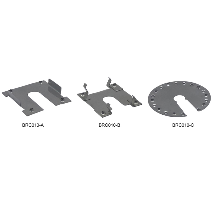
Each fixing through the sheet is a potential leak, and the seal has to survive thermal movement, wind-driven rain and the pressure differences across the roof. Common practice is a sealing washer or gasket beneath the fixing head combined with a calotte or cover that protects the fastener, and the sealing material must be compatible with the sheet coating. Installation quality is decisive here: an over-tightened fastener that deforms the washer, or a fixing drilled at an angle so the seal cannot sit flat, will fail even with the correct component. For a rail system, the sealing detail should be drawn for the actual profile rather than described verbally.
Metal sheets and aluminium rails both change dimension with temperature, and long runs amplify that movement. The design should allow the rail to expand and contract without imposing shear on individual fasteners, typically by ensuring that splices are detailed to accommodate movement and that fixings are not over-constrained along the length of the run. Where a run crosses a building expansion joint, the rail should be interrupted rather than continuous. These are small details in the drawing package and large factors in whether the system is still tight after a decade.
Before committing to a spacing, confirm the actual sheet thickness and the rib geometry on site, then check that the fastener can achieve the required engagement without deforming the profile or tearing the sheet under load. Thin sheets limit the achievable pull-through resistance, and this often becomes the governing limit rather than the rail capacity. Where a sheet is marginal, a wider bearing washer, a different fixing or a secondary member may be required. Testing a representative section can resolve uncertainty faster than further analysis. Where the sheet is marginal, the finding should be recorded in the design file, because it usually explains why the final spacing differs from the earlier concept.
Rail spacing begins with the module. Panel dimensions, the permitted clamp positions along the frame, and the module's own mechanical load rating determine where clamps may sit and how far the rail can be from the module edge. Portrait and landscape orientations change those distances, and bifacial or large-format modules may have stricter clamping zones. This is why the module datasheet should be the first document in the design file and why a layout cannot be finalised before the module is selected. Where the module is changed late in the programme, the rail layout should be rechecked rather than assumed to remain valid, because clamp positions and rail offsets are derived from the frame geometry.
The purlin grid sets where the rail can be supported and therefore how far the rail spans between supports. Longer spans require a deeper section, a thicker wall or additional supports, and the trade-off between rail weight and support frequency is the main material optimisation in a trapezoidal roof system. Because the purlin grid also determines where fixings can land, the layout should be developed from the structure upwards and then reconciled with the module field, rather than the other way round. For a solar rail for trapezoidal tin roof system, the purlin grid is effectively the design constraint that everything else negotiates around.
Design loads come from the site, not from a catalogue. Wind uplift governs on exposed roofs and is significantly higher at edges, corners and ridges than mid-field, so rail and fixing spacing typically differs by zone. Snow load governs in cold regions and depends on the roof pitch and the presence of features that trap snow. Both cases should be evaluated against the governing local standard, and the resulting spacing should be documented so it can be checked on site. A design that cannot state which standard and which load case produced its spacing is not a design.
The practical sequence is to confirm the sheet and substructure, confirm the module and its clamping zones, establish the design wind and snow loads, select the profile, then calculate spacing and support positions. Reorder those steps and the design either over-specifies material or creates a fixing pattern that cannot be built. Super Solar's trapezoidal roof range is described in the trapezoidal roof solar mounting product family, and the company provides free project design support including rail matching and structural calculation so that profile, spacing and support positions are derived from project data.
Rails are commonly supplied in lengths between roughly 2 m and 6.2 m, with custom lengths and pre-punched holes available. Longer lengths reduce the number of splices but are harder to handle and ship, while shorter lengths increase splice count. On trapezoidal roofs, splice positions interact with supports and with the module layout, so cut planning should happen at design stage rather than on the roof. Dimensional tolerance matters as well, because a rail that is out of plane across a large array is visible and complicates clamp installation.
Ask for the material grade, the surface treatment and its thickness, the dimensional specification per profile, and evidence of load testing for wind and snow together with corrosion testing appropriate to the site. Material test reports per batch support traceability, and structural calculations for the project allow the spacing to be defended at approval stage. Where a project requires an authority submission, the documentation set should be agreed at the beginning rather than assembled at the end. It is also worth asking whether the documentation will be issued in a format your own engineer can review directly, since a certificate without the underlying basis is difficult to defend at approval stage.
Long extrusions need protection in transit. Export packaging normally includes a protective film on the rail face, hard cartons and steel pallets, which is appropriate for both sea and air shipment. On site, rails should be stored flat and supported to avoid permanent set, and cutting should be done with a method that does not leave burrs in the slot that interfere with clamp installation. Standard lead times are typically on the order of one to two working weeks, with custom extrusions taking longer, so programme planning should confirm which items are stock and which are made to order.
No, and a table should be treated as a starting point at best. Spacing is a product of the module's clamping zones, the purlin grid, the design wind and snow loads and the governing local standard, and those inputs differ from project to project. Two roofs with the same sheet profile can require very different spacing simply because one is more exposed or carries heavier snow. The correct output of a supplier conversation is a documented spacing for your project conditions, with the calculation basis stated, not a number copied from a brochure.
Not necessarily. A heavier section can carry a longer span or a higher load, but it also costs more, weighs more on the roof and may require different brackets, which can complicate a confirmed design. The engineering objective is the smallest section that satisfies the load case with the required margin at an acceptable support frequency. Oversizing is a legitimate strategy when loads are genuinely uncertain or when future module changes are expected, but it is a decision rather than a default, and it should be recorded in the design basis.
A larger role than most specifications acknowledge. The module frame thickness determines which clamps are compatible, the permissible clamp positions determine how far the rail can sit from the module edge, and the module's mechanical load rating defines the pressure the frame can take. A rail plan that ignores those constraints may be structurally adequate for the rail and still fail the module. That is why the module datasheet belongs in the design file before the rail layout is issued for approval. Suppliers can usually confirm compatibility quickly if they are given the module datasheet, so attaching it to the first enquiry removes an entire round of correspondence.
Verify against drawings rather than impressions. Each penetration type should have a drawing showing the fastener, the seal or gasket, the cover and the contact with the sheet coating. Check that fasteners are tightened to a defined value without deforming the sealing element, that fixings sit perpendicular to the sheet, and that cut rail ends have been finished so they do not trap water. On larger roofs, a first-pass inspection on a representative bay followed by a systematic check of edge and corner zones catches most of the defects before a solar rail for trapezoidal tin roof installation is energised.
 Hot News
2025-11-03
2025-10-22
2025-01-24
2024-06-12
2024-06-12